


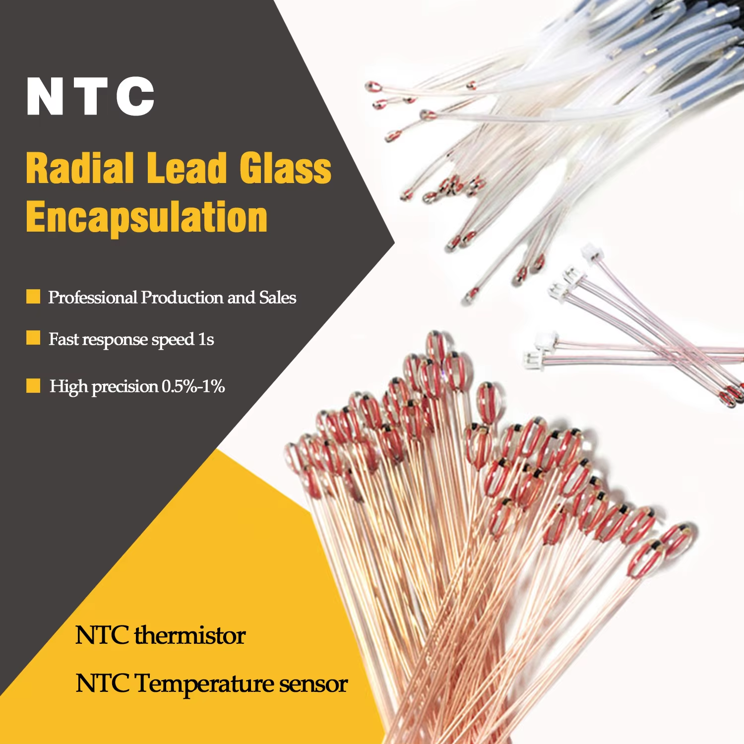
An SMD thermistor is a highly sensitive and miniaturized temperature sensor built from semiconductor ceramic materials and is classified as a Surface-Mount Device (SMD). As temperatures change, miniaturized SMD thermistors change their resistance, allowing for real-time and accurate temperature sensing in tighter and smaller electronic devices. SMD thermistors can be mounted directly on a printed circuit board (PCB). Their small size, along with a quick thermal response, makes them highly desirable for use in modern batteries, automobiles, and all types of systems that require power.
What sets SMD thermistors apart are the different response mechanisms, namely NTC's and PTC's. NTC stands for Negative Temperature Coefficient. As the temperature of NTC thermistors increases, there is a decrease in resistance. This response mechanism makes NTC thermistors ideal for applications that require high accuracy measurements, such as battery management systems and biomedical applications. PTC (Positive Temperature Coefficient) thermistors, on the other hand, have a resistance that increases when a critical temperature is exceeded. This response mechanism makes them useful as self-resetting overcurrent protective devices in electrical supplies and motors.
The distinct differences in response mechanism for NTC and PTC thermistors is a matter of material chemistry. NTC thermistors use a combo of metal oxides materials such as manganese, nickel, and cobolt, while PTC thermistors use barium titanate. The barium titanate thermistors create a breakthrough of resistance at the critical “switch” temperature that is designed to provide a safe operating current < 100 mA. NTC thermistors are primarily used in temperature sensing applications while PTC thermistors are used primarily in protective applications.
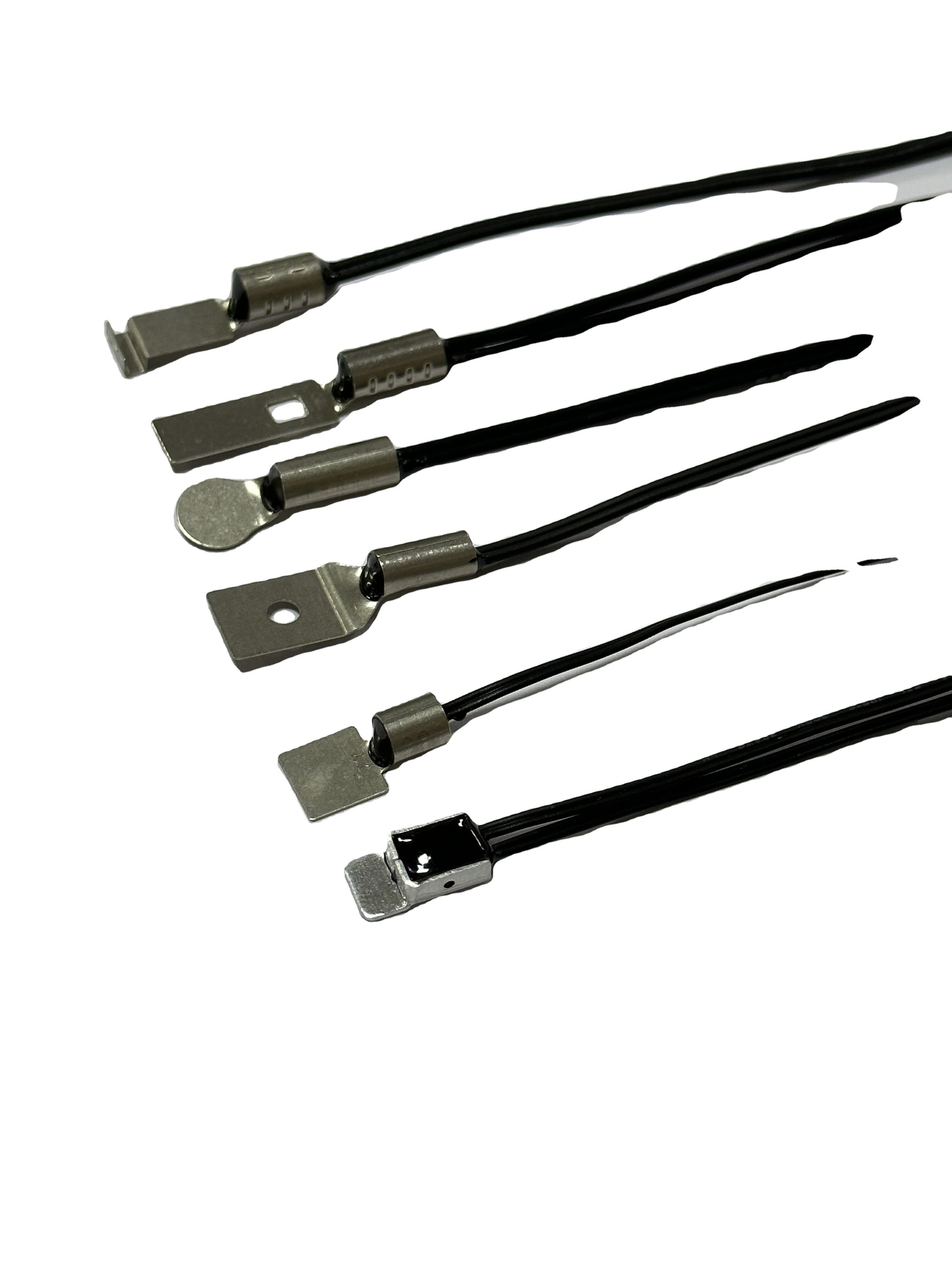
The design of Surface-Mount Device (SMD) thermistors has lead to significant structural advantages. The elimination of standard leaded connectors (a design feature that is standard in non SMD components) allows for direct attachment of the thermistor's flat surface side to the PCB. This direct attachment leads to thermal resistance and therefore provides improved thermal transfer. The direct attachment also leads to improved mechanical support and stability.
- Automated assembly compatibility reduces the variability of manufacturing costs. In combination, hermetic or AEC-Q200 compliant sealing offers a stable solution in humid or thermally aggressive conditions, as well as long-term stability.
SMD Thermistor Critical Selection Criteria
Resistance-Temperature Curves matching
The sensitivity of a thermistor across the system’s operational span is defined by the resistance-temperature (R-T) curve. The nominal resistance at 25 °C (R25) is critical. Higher R25 values reduce self-heating but result in higher electromagnetic interference (EMI) susceptibility. In contradiction, lower values improve noise immunity, but raise thermal drift.
The beta (B) value calculated between two reference temps steers the curve’s steepness. For precise industrial sensors or medical sensors where it is critical to detect sub-degree variations, a B₂₅/₈₅ ≥ 4000 K thermistor is ideal as it provides a fine thermal shift response.
Absolute accuracy across the range of self-heating B-value and tolerance (±1% to ±5%) is determined. In automotive ECUs, where ambient temperature varies between −40 °C and +125 °C, a ±0.5 °C tolerance thermistor can ensure calibration without the need for field recalibration. For consumer grade designs, ±2 °C error is often acceptable.
Self-heating is a significant source of measurement error. For example, 0.1 mW of power dissipated on a sensor creates a measurement error of 0.1°C. There are a number of ways to minimize self-heating:
· Keep excitation current to ≤100 µA
· Use pulsed excitation in battery-powered systems
· Choose higher-R25 variants where applicable in the signal chain
In automotive systems, B-value stability must be verified under AEC-Q200 qualification, including moisture resistance, thermal cycling, and validation of 5,000-hour lifetime testing.
Designing with SMD Thermistors: Layout, Calibration, and Signal Conditioning
The outcome of a precision temperature measurement is a function of a well-thought-out design rather than just smart component choices. For example, a layout that is poorly designed may introduce a measurement error of greater than ±2°C. Similarly, not conditioning a signal is just throwing the data away. There are many sources of error in temperature measurement systems.
Best Practices in PCB Layout to Reduce Thermal Error
Make sure that the thermistors are as far away as possible (≥5 mm) from the sources of heat on the board (like voltage regulators, MOSFETs, etc.) and use thermal relief pads and grounded thermal isolation planes to thermally decouple sensor nodes from board-level gradients. Do not route any high-current traces near the sensing area. For example, 100 mA flowing in a trace that is 2 mm away from the sensing area can create a temperature rise (parasitic heating) of ~0.3°C.
The early detection of hot spots through layout thermal simulation is useful. Some things to consider include:
Copper balancing for thermal mass equalization around sensor pads
Enhanced conduction to inner layers through strategic via positioning under pads
Dampening effects of ambient air currents through conformal coating in environments with variable deployments
Analog Front-End Design: Voltage Dividers, ADC Interface, and Linearization
Design thermistor voltage dividers that use precision resistors (±0.1% tolerance) and are thermally matched to the R25 of the thermistor to minimize gain error. Use an ADC reference voltage ≥1V to mitigate quantization errors in low R25 NTCs. NTCs show non-linear behavior in response to temperature. To accommodate for this, use one of the following methods:
a) implement a firmware piecewise linearization approach with 3 to 5 segments that are defined at the calibration points of interest, such as -10°C, 25°C, 85°C
b) use analog compensation ICs that are designed to produce a near linear response that is a voltage vs. temperature
In precision applications, it is important to limit excitation currents to equal or less than 100 µA. Higher currents may induce self-heating, and artifacts due to thermal response may lead to inaccuracies or a lack of repeatability.
Reliability Considerations and Real-World Applications
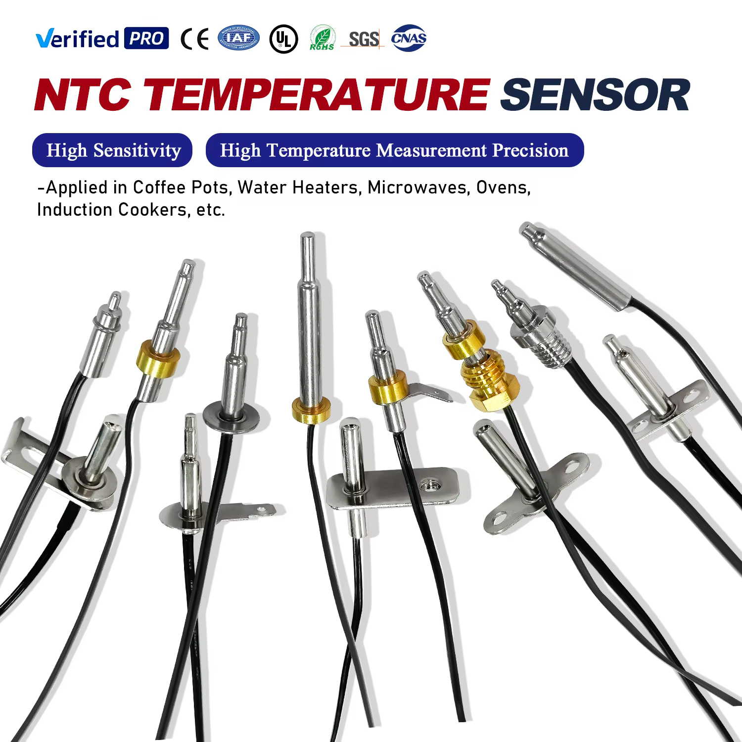
Use Cases in Automotive ECUs, Battery Management, and Power Supplies
SMD thermistors are essential for thermal safety and real-time efficiency:
They support the thermal protection of inductors and transformers from overheating by means of an automatic thermal foldback or shutdown in switch-mode power supplies.
They allow dynamic current limiting to prevent thermal runaway in battery management systems (BMS) by monitoring and responding to cell temperature anomalies during rapid charging and discharging.
They enable real-time monitoring of thermal performance in automotive electronic control units (ECUs) for engine bays, cabins, and traction batteries. This is increasingly important for hybrid and electric vehicles, where the thermal limits are tight, and the consequences of failure are severe.
Lifetime Stability, Moisture Resistance, and AEC-Q200 Compliance
Mission-critical systems must have long-term accuracy. SMD thermistors are stable to within ±0.5°C after 10,000 operating hours, verified to MIL-STD-202 test methods. Moisture resistance rated to IP67 is achieved by epoxy-sealed variants, ensuring HVAC control and outdoor telecom enclosure performance.
Compliance with AEC-Q200 confirms suitability for automotive safety systems. Components are subjected to humidity, 1,000 thermal cycles (−55°C to +150°C), vibration, and solderability testing. Of the thermal-sensor-related recalls, the average cost is $740,000, according to the 2023 automotive reliability study by the Ponemon Institute.
Reliability Factor Performance Benchmark Industry Standard
Operational Lifetime ±0.5°C drift after 10,000 hours MIL-STD-202
Environmental Protection IP67 moisture resistance IEC 60529
Automotive Validation 1,000 thermal shock cycles AEC-Q200
FAQ
What is an SMD thermistor?
An SMD thermistor is a temperature-sensing, semiconductor-ceramic, surface-mount device. It's used for small electronics that have tight spaces and are thermally responsive by directly mounting them on PCBs.
What is the difference between NTC and PTC thermistors?
NTC thermistors have a resistance that drops with pressure. PTC, on the other hand, rise in resistance after a temperature threshold hence the PTC. NTC is favored in scenarios that need a high precision in temperature measurement, PTC on over current scenarios.
How do SMD thermistors improve heat transfer?
SMD thermistors have no leads and attach directly to PCBs, which reduces thermal resistance and improves heat transfer. Because of the direct attachment, thermal lag is minimized that improves mechanical robustness.

